-
[ 데이터통신 ] chapter 4. Digital Transmission전공공부/데이터통신 2021. 4. 15. 14:01
안녕하세요. 개알못입니다~~
이번 포스터는 데이터통신 과목에서 Digital transmission 에 관하여 다루겠습니다.

4.1 Line Coding

- Process of converting binary data to a digital signal.
- Signal level vs data level
The signal levels of values allowed in a particular signal
The data levels of values used to represent data
- Pulse rate vs bit rate
A pulse means the minimum amount of time required to transmit a symbol.
The pulse rate : pulses per second
The bit rate : bits per second
Bit rate = pulse rate x log2L (L : number of data levels)
- DC components
Constant polarity
Undesirable due to reasons
1. A signal may result in errors if the signal is to pass through a system that does not allow the passage of a dc component.
2. DC component is extra energy residing on teh line and is useless.
- Self synchronization
Includes timing information in the data being transmitted.
하나의 신호가 데이터도 전송하지만 동기화도 같이 함.
동기화 시스템 : sender, receiver 시간 맞추기, 오차 일정
- Unipolar encoding
Simple, primitive
Uses only one voltage level : one polarity
1 : a voltage level / 0 : zero voltage level
two problems
A dc component
A lack of synchronization
- Polar encoding
Uses two voltage levels ( one positive and one negative )
alleviated dc component problem
- Polar encoding variations
Nonreturn to zero (NRZ)
Return to zero (RZ)
Manchester
Differential Manchester
- NRZ (Nonreturn to Zero)
positive or negative
there is no zero voltage
- NRZ-L

0 : positive voltage / 1 : negative voltage
Synchronization problem may occur if a long stream of 0s or 1s is given.
In NRZ-L the level of the signal is dependent upon the state of the bit.
- NRZ-I

1 : inversion of the voltage level / 0 : no change of voltage
Better synchronization than NRZ-L
A string of 0s can still cause problems, but because 0s are not as likely, they are less of a problem
In NRZ-I the signal is inverted if a 1 is encountered.
- RZ (Return to Zero)

Uses three values : positive, negative, zero
Changes signal during each bit
1 : positive to zero, positive voltage during a half of bit interval and zero during the rest half
0 : negative to zero, negative voltage during a half and zero during the rest half
Advantages : the most effective synchronization
Disadvantages : more bandwidth than previous schemes, requires two signal changes for one bit
A good encoded digital signal must contain a provision for synchronization.
- Manchester encoding
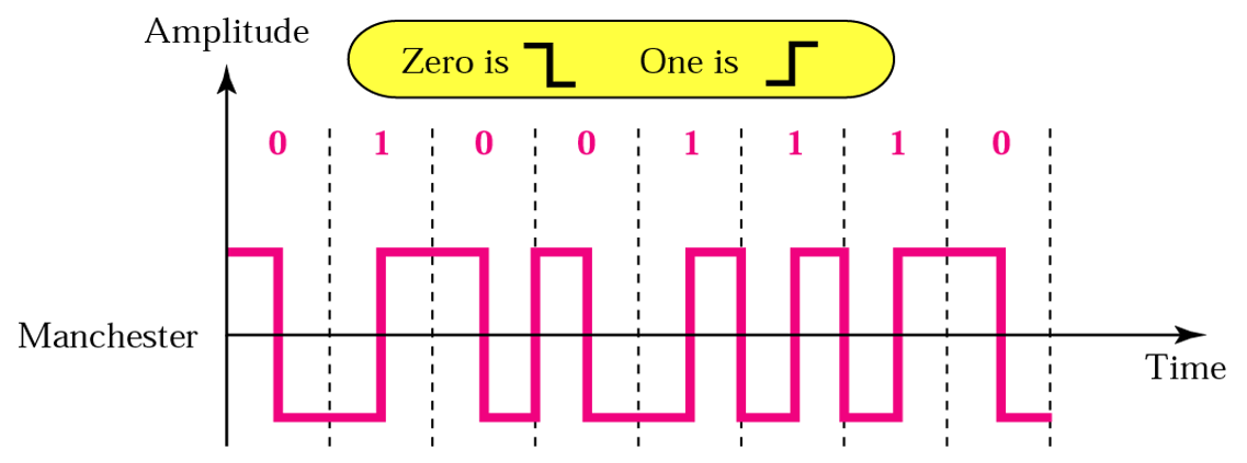
Uses an inversion at the middle of each bit interval
0 : positive to negative transition
1 : negative to positive transition
The same level of synchronization as RZ but with only two levels of amplitude.
In Manchester encoding, the transition at the middle of the bit is used for both synchronization and bit representation.
- Differential Manchester encoding

The inversion at the middle of the bit interval is used for synchronization like Manchester encoding.
The presence or absence of an addition transition at the beginning of the interval is used to identify the bit.
0 : an additional transition
1 : no transition
Advantages : Only one signal change to represent binary 1. / two signal changes for binary 0
The bit representation is defined by the inversion or noniversion at the beginning of the bit.
- Bipolar encoding
Uses three voltage levels( positive, zero )
0 : zero level / 1 : alternating positive and negative voltages
- AMI(alternate mark inversion)

A coomon bipolar encoding scheme
- the term mark comes from telegraphy and means 1
Problems : Synchronization problem for a stream of 0s, especially for long-distance transmission.
- 2BIQ encoding ( two binayr, one quaternary )
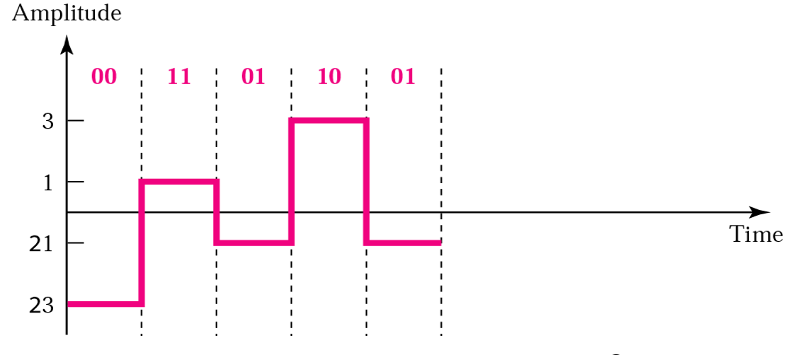
Uses four voltage levels
Represents two bits in each pulse
- MLT-3 encoding (multiline transmission, three level)

similar to NRZ-I, but uses three levels of signals(1,0,-1)
0 : no transition / 1 : one level to the next at teh beginning
4.2 Block Coding
- To improve the performance of line coding ( synchronization problem or bandwidth inefficiency )
- Include some kind of redundancy to ensure synchronization and to detect errors
- Step
Step1 : divide the sequence of bits into groups of m bits
Step2 : Substitute an m-bit code for an n-bit group
Step3 : Use one of the line coding schemes to create a signal
Solve the synchronization and error-detection problems
- 4B/5B encoding
Every 4 bits of data is encoded into a 5-bit code
No more than one leading 0 and no more than two trailing 0s ( 앞에 1개, 뒤에 2개까지만 됨 )
고로 no more than three consecutive 0s. (최대 3개까지 연속으로 가능)
The 5-bit codes are normally line coded using NRZ-I
Disadvantage : increased bandwidth requirement (20%)
Fast Ethernet : 4B/5B encoding with NRZ-I
- 8B/10B encoding
A group of 8-bits is substituted by a 10-bit code
Gigabit Ethernet : 8B/10B encoding
- 8B/6T encoding
Increased bandwidth requirement
Substitutes a 8-bit group with a six-symbol code
Each symbol can have a signal level of 1,0,-1
4.3 Sampling
Q. What if we need to transmit an analog data by nature using a digital transmission technique?
A. Convert the analog data to a digital data using sampling
Q. Why digital transmission of an analog data?
A. To carry the data over a long distance (noise가 끼지 않는다)
Q. 다 디지털 전송을 보내면 되는데 왜 아날로그전송을 하는가?
A. 디지털 전송을 하기 위해서는 Low-pass filter로 된 wide band가 필요하는데, 이게 항상 가능하지 않다. (point-to-point 같은 한정적인 경우만)
그러나 품질을 위해서는 디지털 전송이 좋다.
- PAM(Pulse Amplitude)
Takes an analog signal, smples it, and generates a serious pulses.
Sampling means measuring the amplitude of the signal at equal intervals
폭에 noise가 낄수 도 있음으로 잘 사용하지 않는다.
- PCM(Pulse Code Modulation)
Quantifies the pulses created by PAM to convert the analog data to binary data
PAM > Quantization > binary encoding > line coding
- Sampling rate : Nyquist theorem
The sampling rate must bve at least twice the highest frequency of the original signal for ensuring the accurate reproduction using PAM.
Change a band-pass signal to a low-pass signal before sampling. In this case, the sampling rate is twie the bandwidth.
- Bit rate vs Sampling rate

bit rate = smapling rate x number of bits per sample
4.4 Transmission Mode
- Parallel transmission

Use n wires to send n bits at one time
Advantage : speed
DIsadvantage : cost, limited to short distance
- Serial transmission

Reduce cost as a factor of n
Conversion within devices
Parallel to serial
Serial to parallel
- Asynchronous transmission
The timing of a signal is unimportant
The receiver needs an alert mechanism
Slower due to stop, start bits, gap
Attractive for low-speed communication
Cheap, Effective
- Synchronous transmission
No gaps between bytes
Importance of timing for synchronization at the byte level
Appropriate for high-speed applications due to no need for start/stop bits
참고자료 : Data Communications and Networks, fourth edition by Behrouz A, Forouzan
혼자 공부 중에 정리한 것이니, 질문이나 추가할 부분이 있으시면 댓글 달아주세요 :)
'전공공부 > 데이터통신' 카테고리의 다른 글
[ 데이터통신 ] chapter 6. Multiplexing (0) 2021.04.16 [ 데이터통신 ] chapter 5. Analog Transmission (0) 2021.04.16 [ 데이터통신 ] chapter 3. Signals (0) 2021.04.14